
Easy Rotor Control(ERC) and Yaesu G-450A setup
11/23/2019
After I ordered the Flex, I wanted a way to move the antenna when I wasn’t in the shack. The are some after marker rotor controllers but they are pretty expensive and don’t get the best of reviews. I considering building one out of Arduino following some plans from K3NG. It looks like a fun project but I would want a spare rotor to test with (I looked at the last ham fest but the prices weren’t great on the ones I saw). So I searched for alternatives and found the Easy Rotor Control, ERC v4. I bought the kit version from Vibroplex, which is the US distributor. It arrived 3 days after I ordered it, no tracking was provided. This kit is a board that installs into my Yaesu G-450A to give it a USB port.
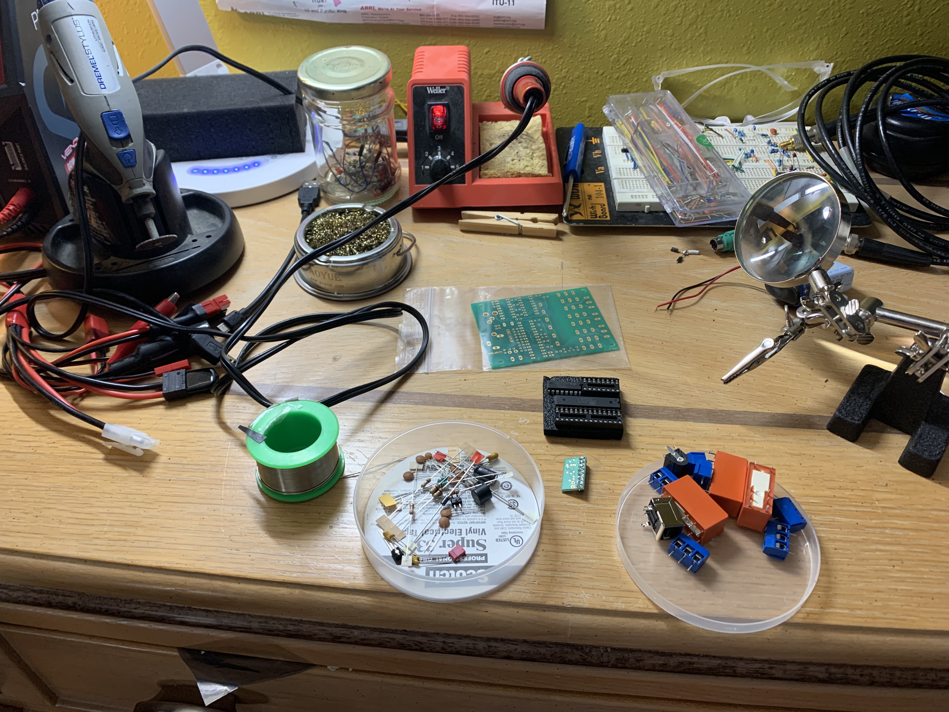
Parts for the ERC v4
It comes with a CD containing the documentation. My shack computer is my last PC that will probably have a CD drive, the instructions are online also. The instructions are not step by step, but a list of parts and a labeled diagram of the board. It’s been awhile since I soldered, but I fell right back into it after a few pins. I had some cold solder joints on the USB daughter board (which was the first thing I soldered). After fixing those the board completed the tests using the program on the CD.
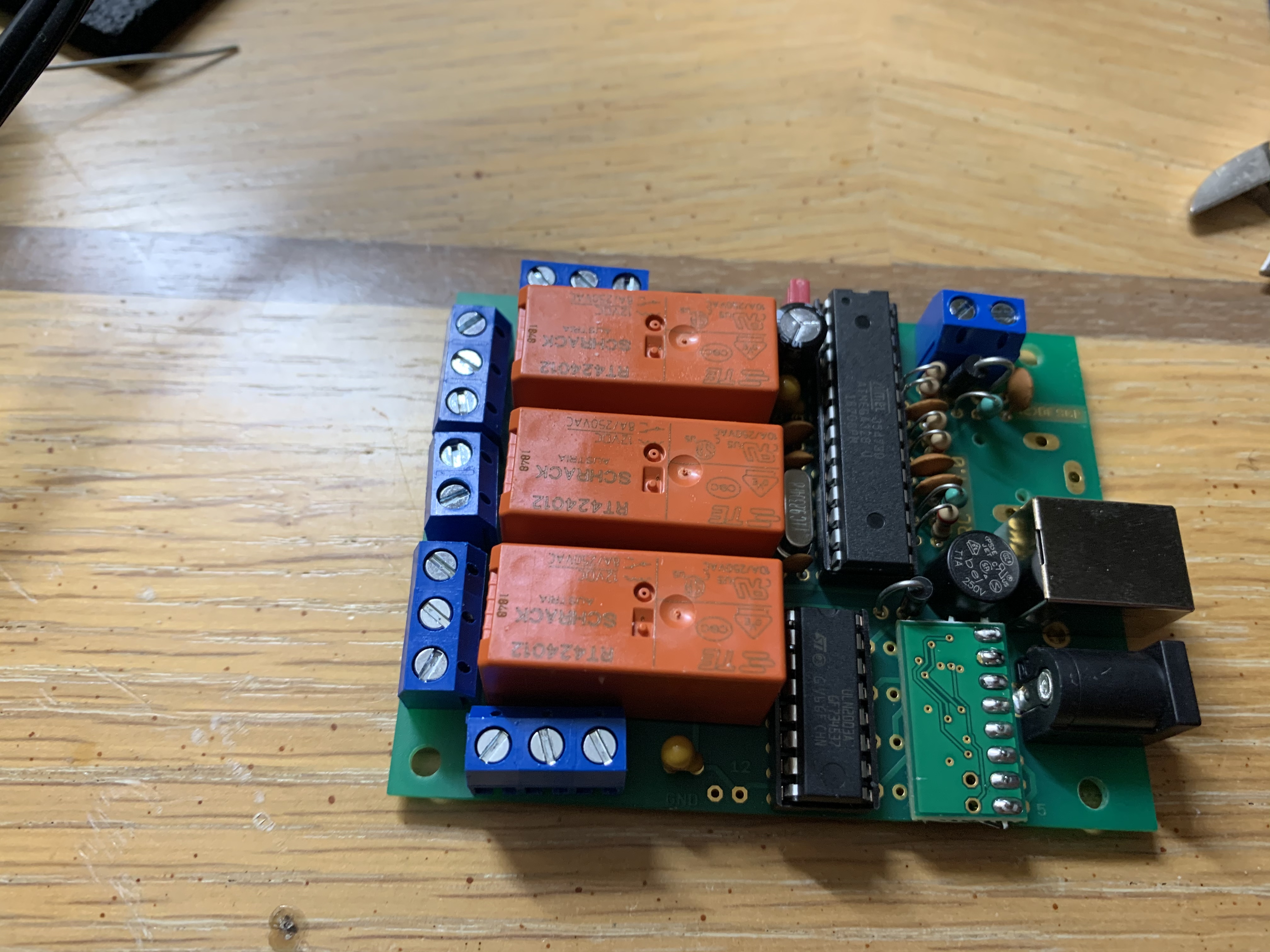
Populated board, basically a microcontroller, USB interface and 3 relays.
I planned to mount the board in the rotor control case. The board comes with a sticker to show you where to drill.
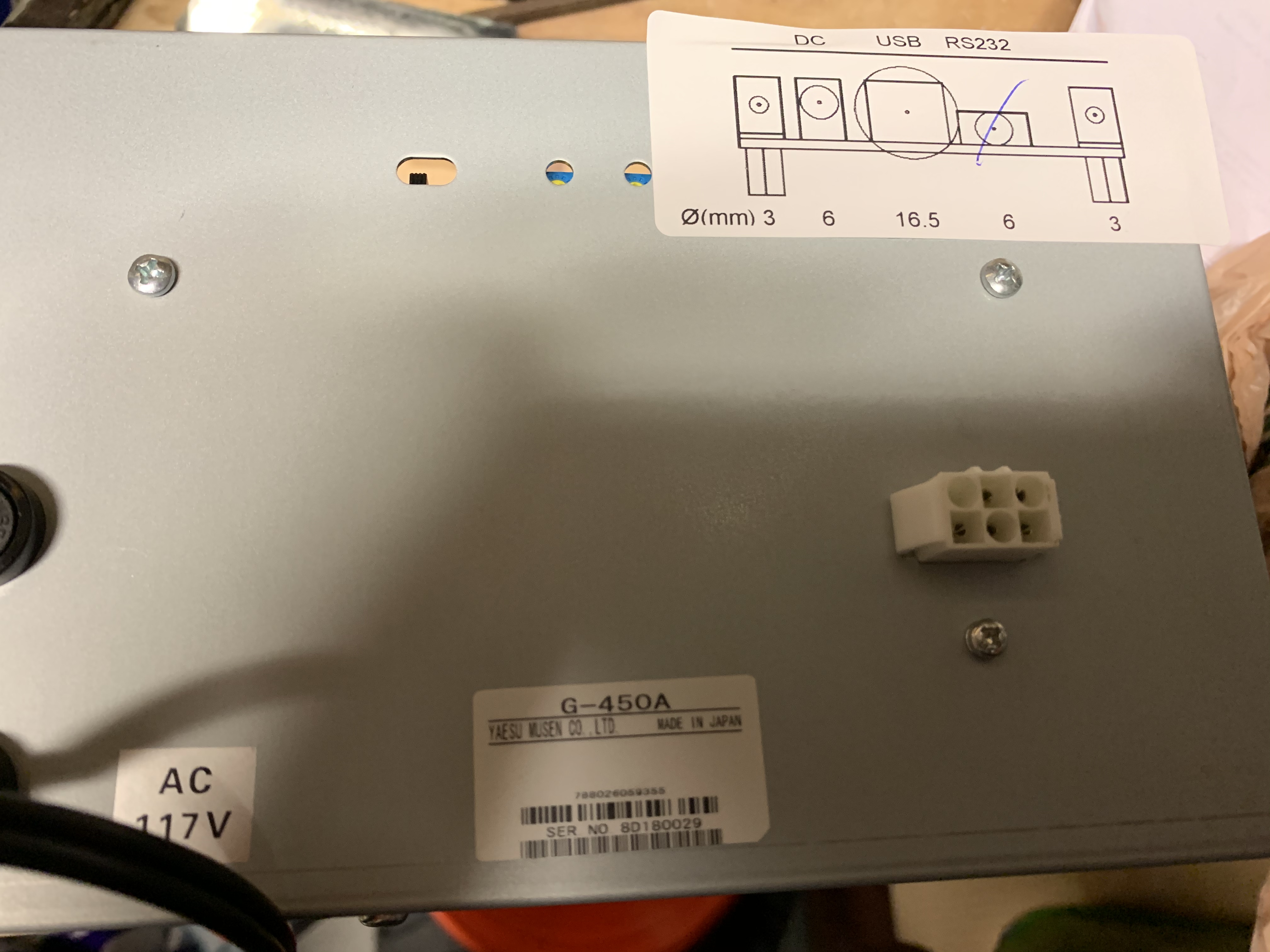
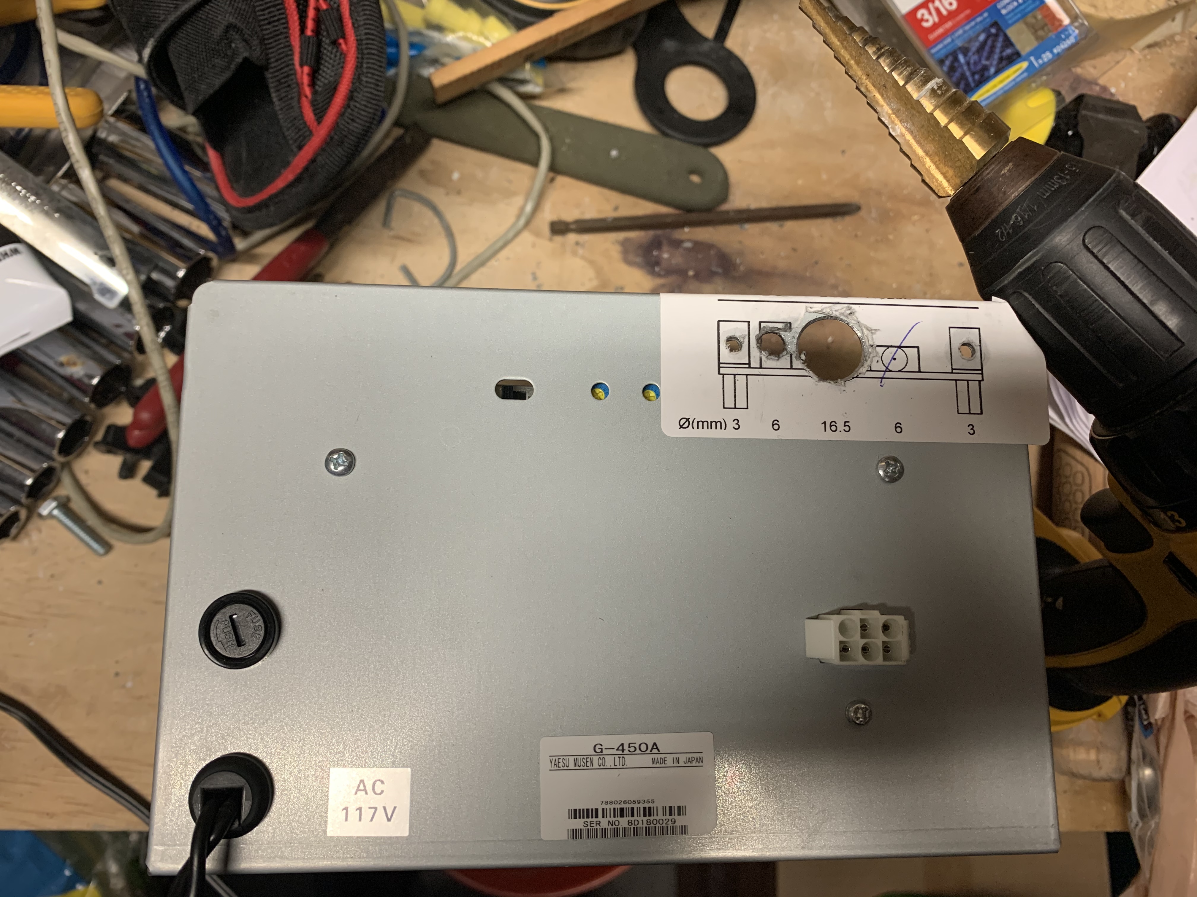
Here the hole’s have been drilled. I used a Harbor Freight step bit for the big hole.
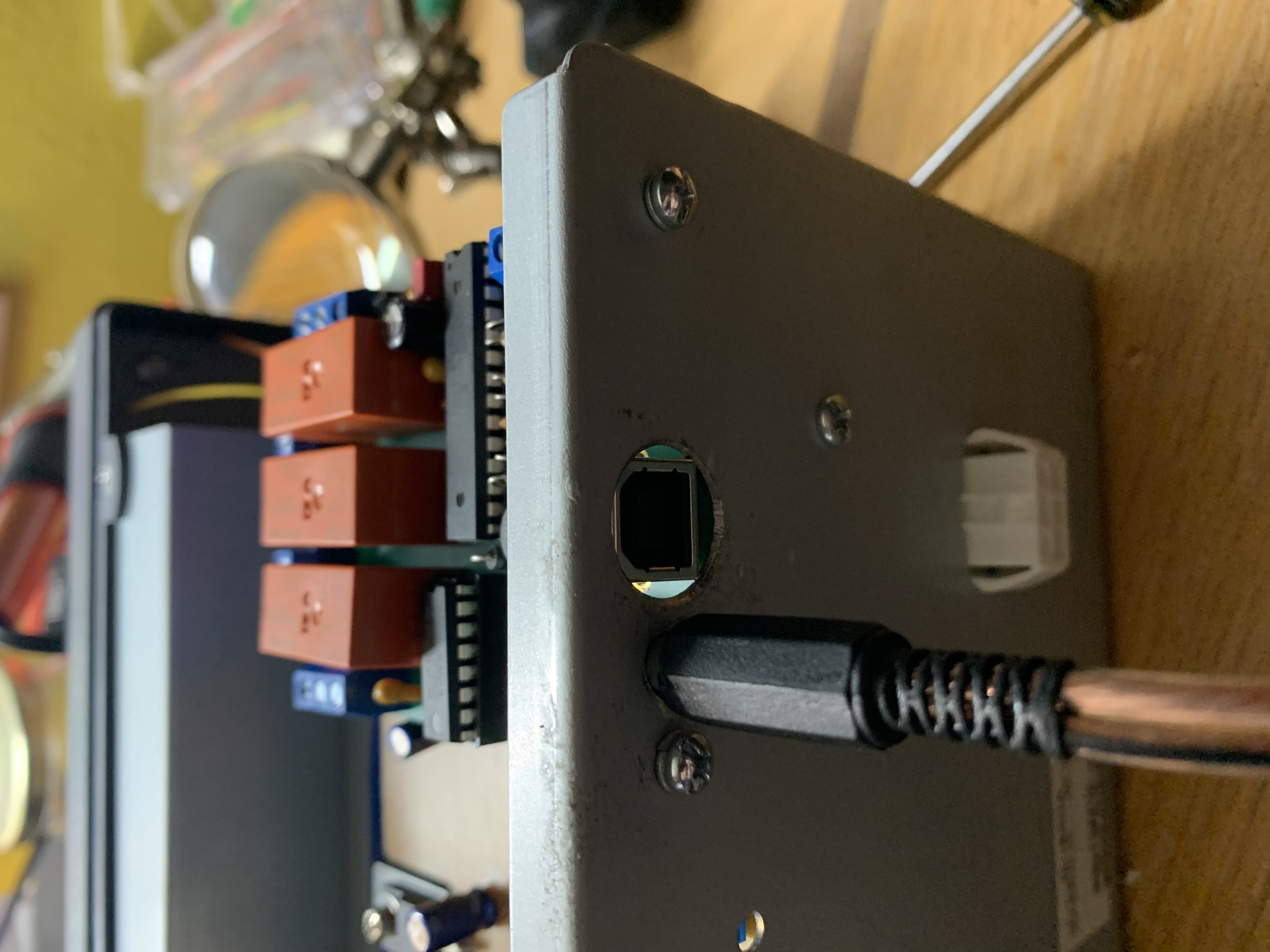
Everything fit nicely and it doesn’t look too bad.
While I was in there I added an azimuthal projection map insert so I aim it better. It’s $15 from axelsandantennas.com (Website no longer available unfortunately). It arrive 5 days after I ordered it as it’s custom made to your QTH. Don’t forget to note where your antenna is pointing before you remove the pointer.
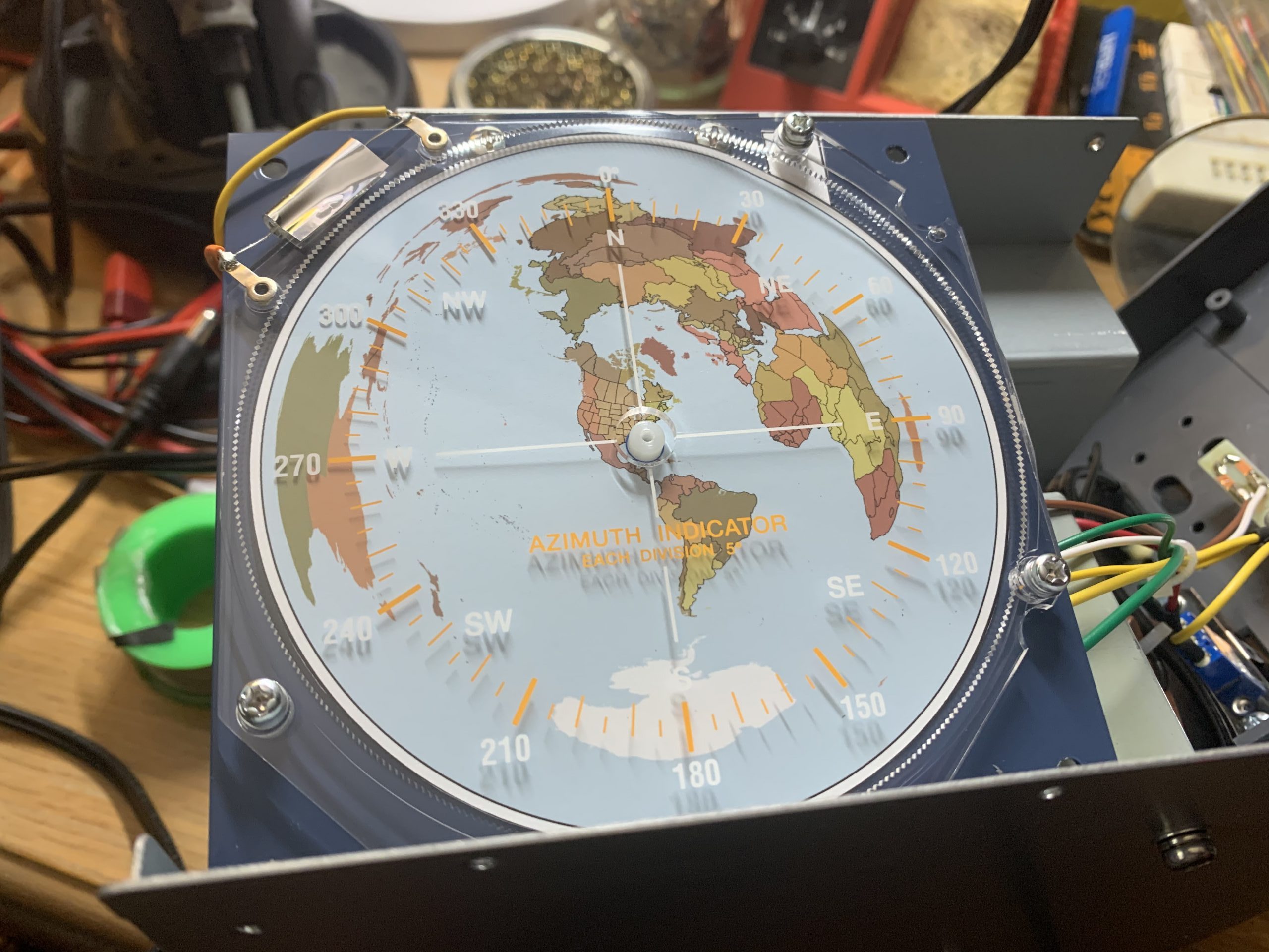
Azimuthal Projection Map insert
There’s 5 wires that need to be connected to the ERC. This was the least fun part of the project as there wasn’t a lot of slack available. I added some extension splices in to make it a litter easier.
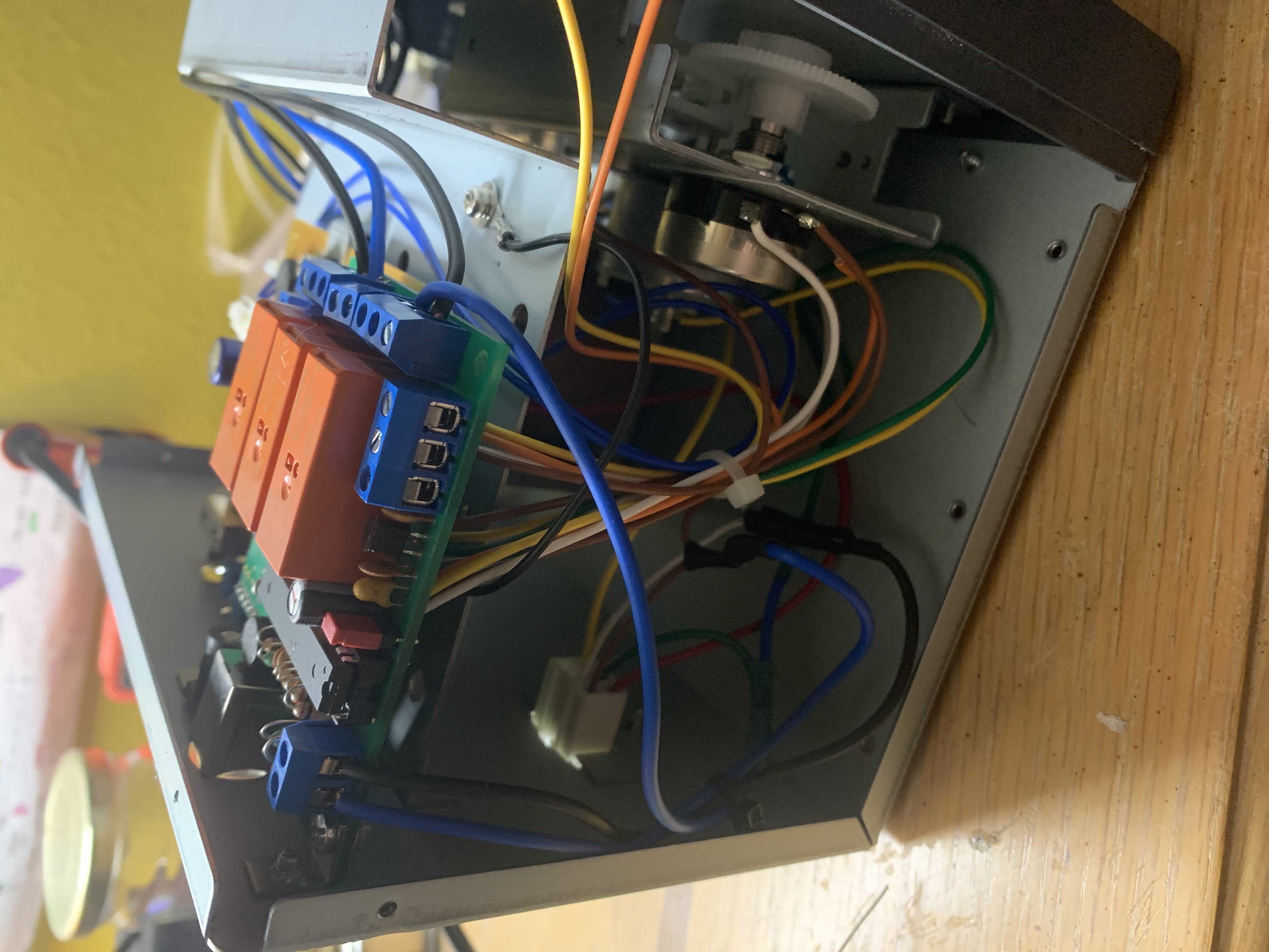
Finished wiring
A calibration the needs to be done after it’s completed. Basically run the rotor to both extremes, then 30 degree steps through one rotation so that it can calculate the voltages. I then hooked it into N1MM’s rotor control and did a few contacts in CQ WW CW. I’d recommend this project to anyone with some soldering skill and a drill, who wants a computer interface to their antenna rotator.
Manual with schematic for the G-450A, most of the manuals I’ve seen don’t have the schematic.